
I would like to share with you my project, building a camera and some other sensors into a dummy camera.
Why?
It started with the desire for outdoor sensors for luminosity and temperature for my home automation system. The best place would be the north side of my house. I considered dedicated hardware but could not find something that appealed to me.
A wall box would be vulnerable for passing scum, so the idea arose to put them in a dummy camera. For getting the data to my home automation system wireless would be the only option. So I needed something to get the data wireless, and that’s when the Raspberry Pi Zero W came into the play. And why not invite a camera module to the party? And perhaps use the Bluetooth functionality, e.g. to control garden IT?
Powering with a battery would be easiest but would need quite some batteries. Of course I did some calculation on the need for current to be expected. I have considered a power bank with a solar panel but could not get it all adequately water proof (ex-ante), including the cabling. So I chose the mains, available in a junction box nearby.
The dummy camera
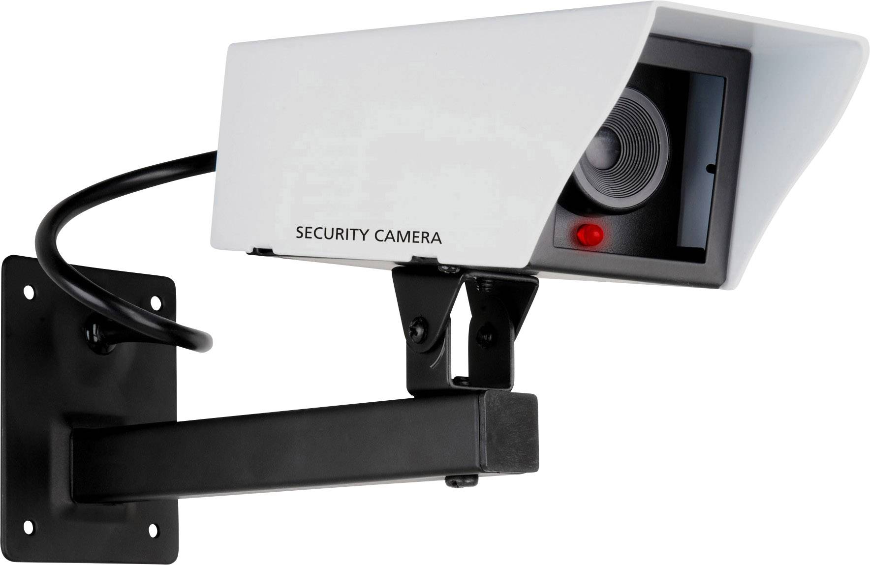
Well, on to searching a dummy camera that could hold a power unit, a zero pi, a camera module and two sensors. The market prefers small and cylindrical, but I needed something boxy and spacious. Long story short, I found the Smartwares CS11D. It’s a simple design that is found under many names but this one has the screws for the top cover on the bottom, so I think it will be slightly better weather proof than others.
Not all screws are willing so some tact is necessary. Inside you find a battery box and a kind of a wall, that on the front side mimics a camera lens and on the back has a small circuit board and some extra mounting points. The circuit board has a blinking led and is wired to the battery box. The extra four mounting points seem to be there for a camera module: it matches nicely, though it could use an extra fraction of a millimetre.
The components
The circuit board holds the led nicely, so I kept it. The smallest capacitor on it conflicts with the camera module though, so I had to remove that and power the led directly through one of the GPIO pins and a ground pin.
Talking about power: that is an issue. I could not find a power unit to build in appliances. I ended up with a power adapter with a USB outlet and a 20 cm short USB cable powering the Zero Pi. I had to demolish the plug to solder a power cord to it, of course nicely insulated with heat shrinks. I fixated the adapter with double-sided tape.
Screws are another thing. You need small ones, really small ones. I bought some King micro-screws online, metrical sizes 1.7 x 8 mm and 1.7 x 6 mm button headed black metal screws, and some brass rings to add spacing. The screws fit nicely through 2 mm holes, and fasten themselves in 1.5 mm holes.
The dummy camera is a metal box with a glass window on the front. That means the onboard Wi-Fi antenna is useless and an external antenna is needed. I found a SMA antenna, a RP-SMA to uFL/u.FL/IPX/IPEX RF cable and a uFL SMT antenna connector. That connector is microscopic and thankfully I found a nearby professional to mount it. The antenna is placed on the back side of the casing after drilling a 7 mm hole.
I fixated the Zero Pi vertically with two pieces of plastic angle profile from the DIY store, 10 x 10 mm, and two screws. As the ribbon cable connecting the camera module has quite some length, I mounted the Zero Pi with its SD card slot towards the camera module.
The two sensors must sense the world outside the dummy camera, of course. The luminosity sensor, a TSL2561, through a 6 mm hole in the bottom I closed with some rigid fully transparent foil coming from a box of pastry and fixated by a ring of glue. The temperature sensor, a SHT31-D, got a same sized window closed with a sample of mosquito bait. The sensors themselves I mounted to the bottom with two screws and some rings.
For the camera I drilled a 9 mm hole in the front ‘wall’. As the connecting ribbon cable fits into the Zero Pi only one way and the Zero Pi has its ISB connectors on top, I placed the camera module so the text is readable upright. I then removed the protective lens covering (the green tab) and mounted the module with two 8 mm screws. It fits great!
Then I soldered the two sensors and the circuit board to the Zero Pi. Keep in mind that too long wiring is less a problem than too short.
Finally I added the adapter and soldered the mains cable on it. I attached the earth wire to a screw and a 20 cm long USB cable to power the Pi. I insulated the mains and – quite important – assured myself with a voltage meter that the casing is not connected to the mains when the Pi is in service.
The software
I mounted Raspbian Lite headless on the camera, and secured it with Clamav, iptables, fail2ban, cron-apt and logwatch.
For the sensors
- I enabled I2C in raspi-config and installed i2c-tools, and with sudo i2cdetect -y 1 I checked the availability of the sensors on I2C.
- I use FHEM as basis of my home automation system, so I installed that on the camera too and linked the camera to my home automation server with FHEM2FHEM.
- I did sudo adduser fhem i2c and sudo reboot.
- In FHEM on the camera I
- defined I2C RPII2C 1
- defined TempHum I2C_SHT3x, attr TempHum IODev I2C, attr TempHum event-on-update-reading humidity,temperature
- defmod Lux I2C_TSL2561 0x39, attr Lux IODev I2C, attr Lux event-on-update-reading luminosity
- In FHEM on the server I defined the dummy modules TempHum and Lux.
Now I can use the sensor data in my home automation rules.
For the blinking led
- I did sudo adduser fhem gpio ; sudo reboot.
- In FHEM on the camera I
- defined BlinkingLed RPI_GPIO 21, attr BlinkingLed direction output
- defined Blinking at +*00:00:10 set BlinkingLed on-for-timer 0.1
- defined BlinkOnAtSunset at *{sunset()} attr Blinking disabled 0
- defined BlinkOffAtSunrise at *{sunrise()} attr Blinking disabled 1
Getting the signal from the camera module to my Synology Surveillance Station turned out to be a project on its own, and will be covered in another post.
